Understanding the Different Types of Custom Gears
Gears are fundamental for transmitting power and motion between machine parts, making them indispensable in many sectors, from automotive and aerospace to industrial machinery and consumer electronics.
The selection and design of gears directly impacts the efficiency, durability, and performance of mechanical systems.
In this guide, we’ll discuss some of the most common types of custom gears available on the market so you can make a more informed decision on which one you need for your unique application.
The Basics of Customization
Before we discuss the different types of gears, there are several terms and facts you need to know that serve as starting points for customizing gears:
Z
The number of teeth on the gear, most commonly abbreviated to Z in gear-related equations.
Diametral Pitch (DP)
Diametral Pitch is commonly referenced in countries that use imperial units. It measures the size of the gear teeth and is calculated by dividing the number of teeth by the pitch circle in inches, so it is the number of teeth per inch, which is not always a whole number. The larger the DP, the smaller the teeth.
Module
This is the ISO standard used to measure the size of gear teeth. It is a direct measure of gear tooth size, so the larger the module, the larger the tooth. DP can be converted to a module by dividing 25.4 by the DP.
Pressure Angle (PA)
PA is the angle through which force is transmitted between meshed gears. It is important because it affects tooth strength (and the power that can be transmitted), gear wear, operating noise, and meshing interference. Larger pressure angles result in stronger teeth, but it will increase gear wear and operating noise. Smaller pressure angles make for weaker teeth but a quieter drive and easier meshing of gears. Most modern gears use a 20-degree pressure angle, though older drives often use 14.5-degree, which is quieter but not as strong.
Face Width
The axial width of the gear surface. A wider face can transmit more power but takes up more space and has more inertia.
Material
Gears are made from many different materials, but the most common are cast iron, steel, and plastics.
Types of Gears
Spur Gears
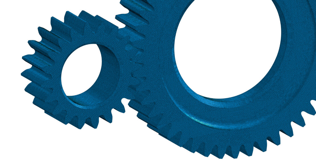
Spur gears are characterized by their straight teeth, which are cut parallel to the gear’s axis. This straightforward design allows for uniform tooth loading and minimizes complex stress patterns. The simple design of spur gears makes them easier to manufacture with high precision, especially when custom specifications are needed.
Advantages
- Efficiency: Spur gears are highly efficient because of their simple design, ensuring minimal energy loss in power transmission.
- High Load Capacity: Their straight teeth design allows uniform load distribution across the entire tooth face, making them ideal for high-load applications.
- Precision & Reliability: Their simple design also ensures precise and reliable operation, crucial in applications requiring exact timing and synchronization.
- Versatility: They’re adaptable in terms of size, materials, and tooth specifications, which makes them suitable for many applications.
Common Applications
The primary function of spur gears is to transmit motion and power between parallel shafts in machinery. This makes them ideal for the following applications:
- Food & Beverage Production: Here they provide synchronization of the various machinery on production lines to quickly prepare and package foods and beverages.
- Automotive Transmissions: Spur gears are used in this application because of their ability to reliably and efficiently transmit power from the engines to the wheels.
- Industrial Machinery: They are used in lathes, milling machines, and other industrial machinery where precise motion control is needed.
- Consumer Electronics: They are also found in smaller devices, such as printers and household appliances, where quiet gear operation is beneficial.
Helical Gears
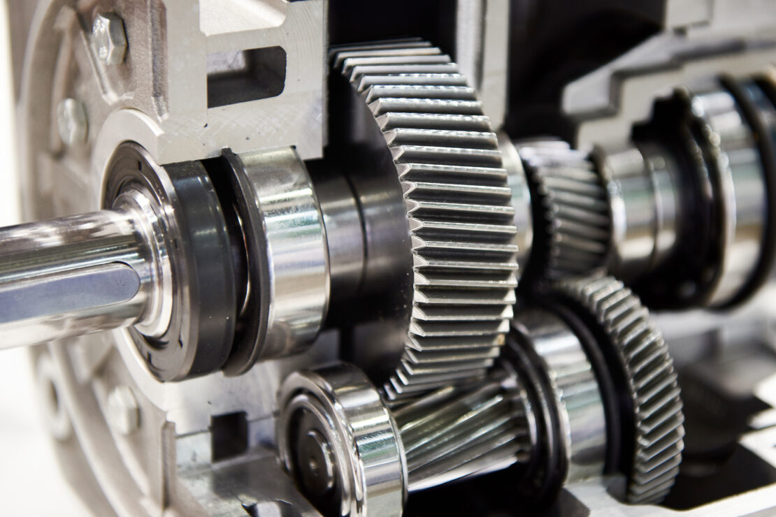
The defining feature of helical gears is their angled teeth. This angled design allows the teeth to mesh gradually, starting from one end of the tooth to the other, as opposed to the simultaneous engagement seen in spur gears. This gradual engagement results in a smoother and quieter operation. Additionally, the angle of the teeth can be customized to meet specific needs.
Advantages
- Smooth & Quiet Operation: Their unique angled tooth design makes them ideal for high-speed or noise-sensitive applications.
- Higher Load Capacity: Due to the increased surface contact between meshing teeth, helical gears can handle higher loads than spur gears of the same size.
- Durability: The smoother operation results in less wear and tear over time, extending the life of the gear.
- Mounting Versatility: Helical gears can be used in both parallel and crossed-shaft applications.
Common Applications
- Automotive Transmissions: Because helical gears operate smoothly and have a higher load capacity, they are often used in car gearboxes.
- Conveyors: Helical gears are used to move large loads on long conveyors found in heavy industry.
- Industrial Machinery: They are used in machines that encounter heavy loads, such as pumps, aggregate mixers, and crushers.
- High-Speed Machinery: Their smooth operation is also beneficial in machines operating at high speeds, where noise and vibration reduction are crucial.
Rack Gears
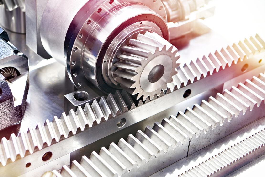
Rack gears, a distinct gear mechanism, are characterized by their linear rather than circular design. They consist of a straight bar with teeth along one side, functioning as a segment of a gear wheel stretched out into a straight line. This design allows the rack gear to convert rotational motion into linear motion. The size and spacing of the teeth on the rack gears can be customized based on the application requirements.
Advantages
- Conversion of Motion: The primary advantage of rack gears is their ability to convert rotational motion into precise linear motion, which simply cannot be done with traditional circular gears.
- Uniform Motion: Rack gears provide uniform motion along the linear path, ensuring consistent performance in applications requiring straight-line action.
- No Limit on Distance: Unlike circular gears, which are limited by their circumference, rack gears can be made to any length, allowing for extended linear movement.
Common Applications
- Automotive Steering Systems: Linear motion is required to turn the wheels of a car, so rack gears are a necessity in steering systems.
- Automation & Robotics: Robotic arms and automated material handling systems require precise linear motion, making rack gears vital.
- CNC Machines: They are also used in CNC machines for accurate linear positioning of the tool or workpiece.
- Rail Systems & Sliding Gates: Rack gears are effective for any application requiring long, straight motion, such as in rail systems and sliding gates.
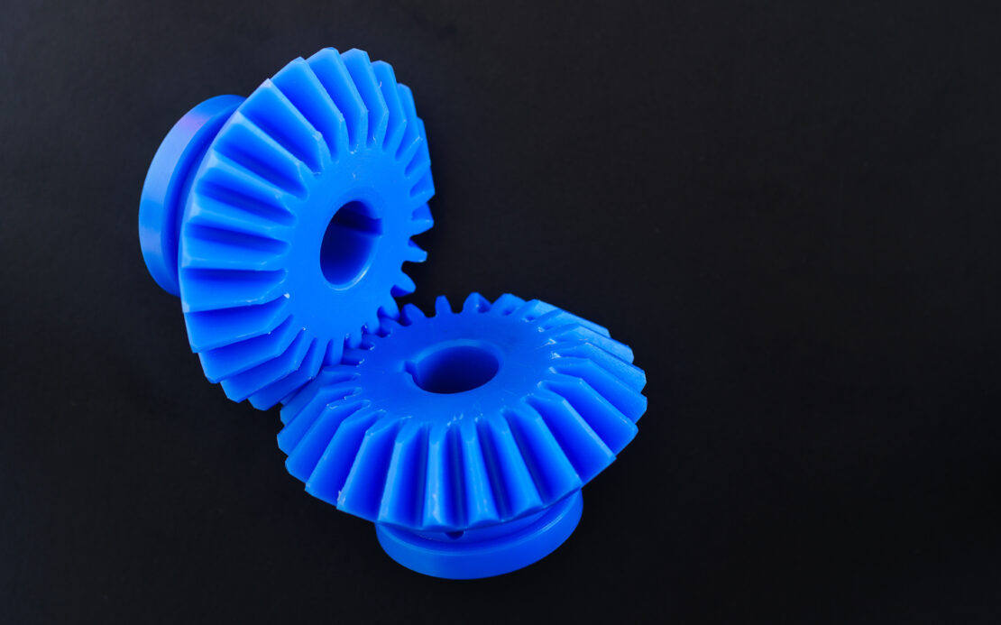
Bevel Gears
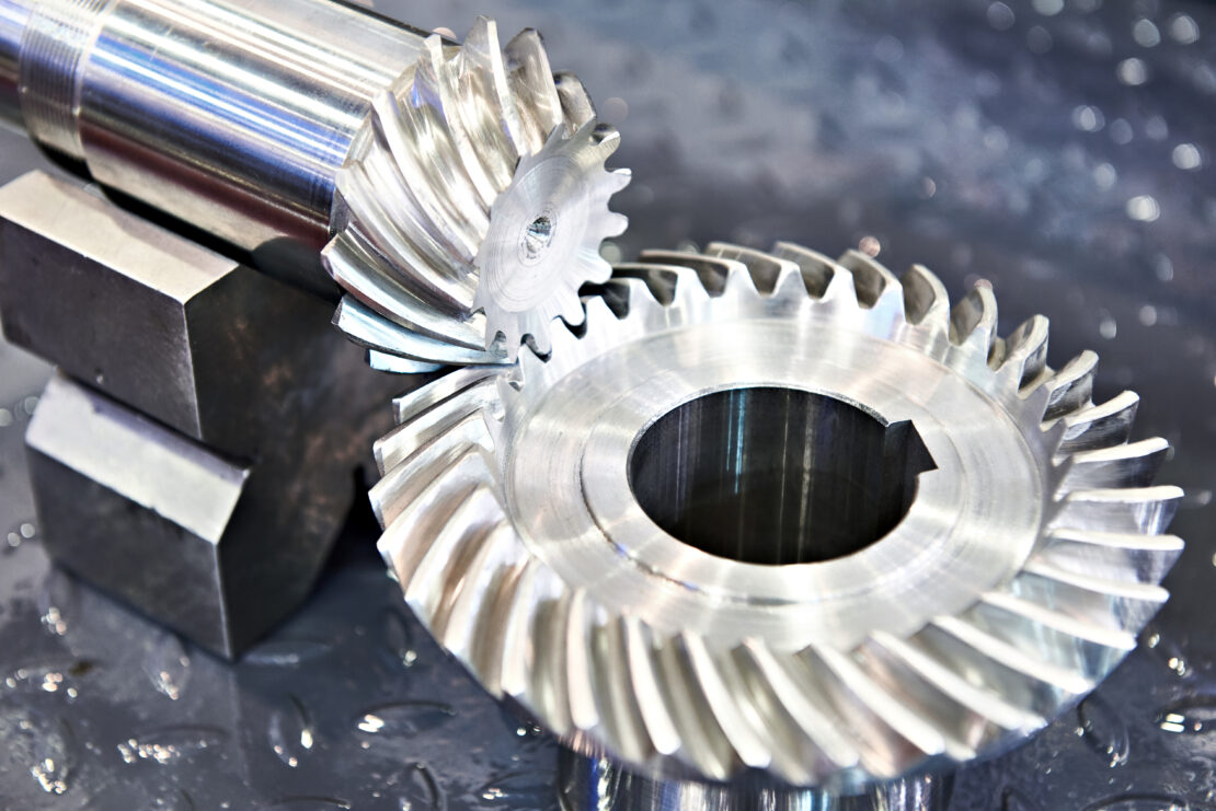
Bevel gears are primarily used to transmit motion between intersecting shafts. They are characterized by their conical shape, which allows them to mesh with another bevel gear at an angle (typically 90 degrees, but other angles are possible).
The teeth of bevel gears can be straight, spiral, or hypoid—each variation offers different performance characteristics. Straight bevel gears, as the name suggests, have straight teeth, while spiral bevel gears have curved teeth and offer smoother and quieter operation. Hypoid bevel gears are similar to spiral bevel gears, except they allow for the axes of the gear to be offset from each other, providing more design flexibility.
Advantages
- Versatile Angles of Operation: Bevel gears are ideal for changing the direction of shaft rotation, allowing motion transmission at various angles.
- Compact & Efficient: Their conical shape makes them more compact and efficient in transmitting power in applications with limited space.
- High Torque Capability: Bevel gears can handle significant amounts of torque, which makes them ideal for heavy-duty applications.
Common Applications
- Automotive Differential: Bevel gears are a key component in vehicle differentials, allowing the wheels to rotate at different speeds, especially when turning.
- Power Tools: These gears are used in drills and other power tools where a change in the rotation axis is required.
- Industrial Machinery: Bevel gears are needed in heavy machinery where shafts intersect.
- Aerospace Applications: Their ability to handle high torque and transmit power at various angles makes them suitable for many aerospace mechanisms.
Miter Gears
Miter gears are a subtype of bevel gears, but there’s a significant distinction between the two. Miter gears are specifically used in applications where the shafts intersect at a right angle and where the speed and torque need to remain constant from input to output. Comparatively, bevel gears can have different numbers of teeth on each gear and can be designed for speed ratios other than 1:1.
Advantages
- Equal Speed Transmission: Their 1:1 speed ratio is perfect for applications that need to maintain a consistent speed between the input and output shafts.
- Compact Design: Like bevel gears, miter gears are ideal for tight spaces where transferring motion at a 90-degree angle is needed.
- Simplicity & Efficiency: Their design is straightforward, making them efficient and reliable for right-angle power transmission.
Common Applications
- Precision Instruments: Precision instruments, like optical devices, spectrometers, clocks, and CNC machines, use miter gears for exact 90-degree angle motion transfer without altering the speed or torque.
- Power Transmission in Tight Spaces: Due to their compact size, they are ideal in applications with limited space and where right-angle motion transfer is required.
- Certain Automotive & Machinery Applications: Miter gears play a crucial role in vehicle differential systems, power take-off systems, rotary tables, and some conveyor systems to ensure consistent speed and power transfer along different axes.
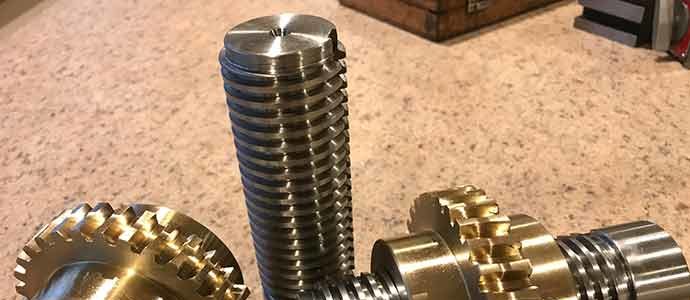
Worm Gears
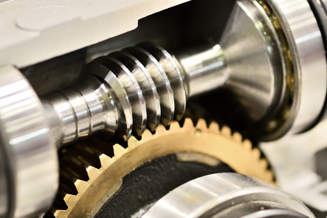
Worm gears are known for their distinctive design and use in specialized applications. These gear types consist of two main components: a worm, which is similar to a screw, and a worm wheel, resembling a segment of a helical gear. This design allows for significant reduction ratios in a very compact space. The worm’s angle is shallow; as a result, the contact with the worm wheel occurs over a large area, providing a high level of friction and an exceptionally smooth operation.
Advantages
- High Reduction Ratios: Worm gears can achieve very high reduction ratios compared to other gear types.
- Compact & Quiet Operation: Their design allows for considerable power transmission in a relatively small space, and they operate more quietly than most other gear types.
- Self-Locking Feature: In some cases, worm gears can be self-locking, meaning the worm cannot be driven by the worm wheel. This feature is useful in applications where a system should not move under load when power is not applied.
- Smooth Transmission of Motion: The gradual engagement of the worm and the worm wheel ensures smooth motion transmission, reducing shock and vibration.
Common Applications
- Lifting Mechanisms: Worm gears are typically used in hoists and elevators, where the self-locking feature works as an additional safety mechanism.
- Conveyor Systems: Some conveyor systems use worm gears to control the speed of the conveyor belt more smoothly.
- Tuning Mechanisms: Worm gears are used in musical instruments like guitars because they allow for precise and smooth tuning.
- Heavy Machinery: Worm gears are used in some industrial applications, particularly where large gear reductions are needed in a limited space, such as in presses or mining equipment.
- Automotive Power Steering: Worm gears are also used in power steering systems to reduce the effort needed to turn the steering wheel.
Choosing the Right Gear Type
As with most components, application requirements will guide the selection process. Typically, you would want to look at speed requirements, torque demand, direction of motion, space constraints, noise and vibration sensitivity, and load distribution.
Let’s break these factors down more:
Speed Requirements
If the primary requirement is high-speed transmission with less concern about torque, spur or helical gears are often suitable due to their efficiency and ability to handle high-speed operations smoothly.
However, if your application requires variable speeds, consider using step pulleys or a combination of different gear types to achieve the desired speed range.
Torque Demands
Worm gears are ideal if your application requires high torque at low speeds because of their high reduction ratios and self-locking capabilities. If you need more balance between speed and torque, bevel or helical gears may be better because they can handle varying loads efficiently.
Direction of Motion
Bevel gears, including miter gears, are perfect for applications requiring a change in motion direction, especially at a 90-degree angle, but rack gears are the go-to choice for applications requiring the conversion of rotational motion to linear motion. If you need smooth, parallel motion transfer, spur or helical gears could be ideal, while both helical and worm gears are especially effective in applications where the motion needs to be transferred between non-parallel, usually perpendicular shafts.
Space Constraints
Choose compact solutions like worm gears or bevel gears in systems where space is limited. They can provide high reduction ratios in a smaller footprint.
Noise & Vibration Sensitivity
Helical gears are preferable if noise and vibration need to be minimized due to their gradual engagement and smoother operations.
Load Distribution & Wear
Gears like helical and worm gears offer better load distribution across their teeth, leading to potentially longer gear life.
| Characteristics | Spur Gears | Helical Gears | Rack Gears | Bevel Gears | Miter Gears | Worm Gears |
| Speed | High | High | Variable | Variable | Fixed (1:1) | Low |
| Torque | Medium | High | High | High | Medium | High |
| Direction of Motion | Parallel | Parallel/Slightly Angled | Linear | Perpendicular/Variable Angles | Perpendicular (90 Degrees) | Perpendicular |
| Good in Limited Spaces | No | No | Yes | Yes | Yes | Yes |
| Reduces Noise & Vibration | No | Yes | No | No | No | Yes |
| Can Handle Heavy Loads | Yes | Yes | Yes | Yes | Not Recommended for Heavy Loads | Yes |
Get Help Selecting the Right Custom Gear
Choosing the wrong gear type means inefficient power transmission, higher energy consumption, reduced output, excessive wear and tear, and potential system failures.
If you’re still not sure which type of custom gear you need, contact Motion Systems. Founded in 1973, we manufacture a wide array of custom power transmission components, including gears. We proudly make all components in the United States and can even provide expedited services.
Please contact us today to learn more about our manufacturing capabilities or to request a quote.